software for smart card reader writer
By smartcard456
@smartcard456 (1)
India
August 25, 2006 2:18am CST
IntroductionGO UP
This is a Smartcard (ISO 7816) Serial Reader / Writer, also know as "Phoenix" Interface.
This adapter must be connected to 9 PIN PC serial port
Circuit descriptionGO UP
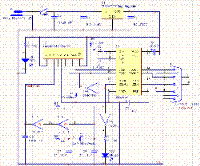
The MAX232 converts the RS-232 levels (about +10 and -10 V) to TTL voltage (0 and +5 V) and vice versa without requiring anything else than +5 V power supply. This chip contains two TTL-RS-232 and two RS-232-TTL drivers and needs four external 1 uF capacitors in order to generate the RS-232 voltage internally. The adapter electronic gets its power supply from the smartcard reader device VCC line or you can use an external 5 V supply if you wish.
The card slot's RST line is connected using one of the TTL-RS-232 drivers in the MAX232 to DCD, so that the software and the reader can easily resynchronize in case of a protocol error.
The I/O line is a bidirectional half-duplex asynchronous TTL level serial port.
We can connect this line to a MAX232 TTL input driver (which is connected to RxD and sends bytes to the PC) in order to receive data from the card. The TxD signal is converted in the MAX232 to TTL level and is connected with an open collector TTL driver to I/O. This open collector driver (one of six in the 74LS07) has a high impedance output during idle state and 1 and is connected to GND during a 0 on it's input. The R4 (a pull-up resistor to +5 V on I/O) guarantees that the adapter is in high impedance state if the TxD line is idle and delivers the correct voltage if the PC sends bytes and the smartcard is in reception mode. As we don't connect totem-pole or tristate outputs to I/O, a short circuit should be impossible in the adapter.
Pay attention to the polarity of the capacitors (marked with a + in the diagram next to each capacitor)! The ---- symbols in the MAX232 diagram above indicate the voltage converters inside the chip.
The RED LED show you when the reader is powered.
The GREEN LED show you the I/O traffic.
As a side effect of this simple interface design, every byte sent by the PC is at the same time also received by the PC. Consequently, you can test the circuit with a terminal emulator by switching off local echo: if you still see every typed character immediately on the screen, the interface should be all right.
Software must be capable of dealing with this echo from the interface.
Components ListGO UP
Designator description Value
C9 Capacitor 27 pF 16V
C8 Capacitor 27 pF 16V
R4 Resistor 22 KOhm
R1 Resistor 220 Ohm
R2 Resistor 220 Ohm
R3 Resistor 47 KOhm
R6 Resistor 2.2 KOhm
R5 Resistor 1 MOhm
Y1 Crystal Oscillator 3.579 MHz Quartz
U4 Hex Inverter 74HC04N
U3 Hex Buffer / Driver with Open-Collector High-Voltage Outputs 74LS07N
U2 +5V Powered RS-232 Driver/Receiver MAX232
J1 Serial Connector DSUB 9 PIN FEMALE
JP1 Smartcard Connector ISO 7816
DS1 Red LED RED
DS2 Green LED GREEN
P1 2-Conductor Plug Power Plug +9V / +12V
C4 Polarized Capacitor (Radial) 1 uF 16V
C3 Capacitor 0.1 uF 16V
C2 Capacitor 0.33 uF 16V
C5 Polarized Capacitor 1 uF 16V
C7 Polarized Capacitor 1 uF 16V
C10 Capacitor 100 pF 16V
C6 Polarized Capacitor 1 uF 16V
C1 Polarized Capacitor 470 uF 16V Elettr.
U1 Positive Voltage Regulator 7805 +5V Voltage Regulator
S1 Switch Single-Pole, Single-Throw
1 response


